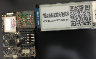
A Library for Interfacing a generic E-Paper Display with Microsoft Azure Sphere device on Avnet Azure Sphere Starter Kit
The project implements a Standard Interface abstraction layer that abstracts the common functions used by each end display into AzSphere_Interface files, and subsequently the main end functions into the respective epd files.
First of all Wishing you Merry Christmas and a Happy New Year. I am finally Restarting the blog I started few years ago, and what's more fun than getting rid of storage devices occupying my damn USB ports ( @all MAC users You know What I mean ;-) )!!
So, Lets get started.
Now there are many wireless storage devices like these that costed me about 3K INR !! hey but where is the fun of learning there ?
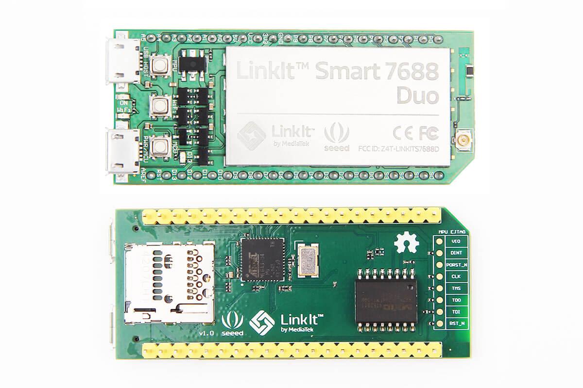
So, I went with buying a Linkit Smart 7688 Duo Board that costed me about 1.6K INR and as I already had a 64 GB Memory card laying around; Why not build something like this using
Linkit Smart?
1. Introduction
Linkit Smart 788 Duo is a Small development platform based on OpenWRT, i.e. the same tiny footprint linux based OS running on your routers, Arduino Yun (now changed to Linino OS), and many other development platform. Below listed is some technical data for NErDS!!
So, basically this board is a tiny computer running tiny version of Linux which comes in a tiny box :).
2. BASIC CONFIGURATION
Well next I wanted to get an SD card and mount it on the device; Obviously a 32 MB flash wont even hold anything :( . So we get our mighty 64 GB Memory card laying around and insert it. :D That was easy :)
Ohh boy,; But how to access the card or the device ?
For now just follow the steps, we will cover the later in detail :)
Step1 : Connect Linkit Smart (Left most usb with pwr/mcu label) to power adapter (5v at least 500mA). Ensure green light turning on. The orange light will glow once and then will glow again for about 10 sec before blinking.
Step2 : Connect to the Wirless network created by linkit one something like this LinkIt_Smart_7688_XXXX.
Step3 : Open a web browser and type http://mylinkit.local/
Step4 : The web page will ask you to setup a new password for root. Do that and login on to the page.
Step5 : Find "Current IP Address" tab and note down your IP address.
Step6 : Open your terminal and type
ssh root@<IP_ADDR> (Replace <IP_ADDR> with IP address )
t will ask you to enter your password. Enter that and you are in :)
Now that the card is in , We need to mount the card; well before that I thought, why cant we boot the entire system from the memory card itself ?? Why to boot from 32 MB raw flash that seems to have a limited write cycles ? So a little googling fetched me this
This is an essential step as you are now booting the device from the SD card. Don't worry if you are not able to understand this just copy paste the commands given in the above link and you are good to go
3. CREATING NETWORK SHARES
Well now that we have our base ready, all we have to do is sharing a folder that we can access from anywhere. We will do this using openWRT console.
STEP 1 : Create a folder to share. Type the following on your terminal
cd /root
mkdir AirDrive
chmod o+rwx /root/AirDrive
chown nobody /root/AirDrive/
STEP 2 : Open a web browser and type http://mylinkit.local/ ;Clicko Go to OpenWrt
STEP 3 : Login using username root and your password.
STEP 4 : Click on the Services tab.
STEP 5 : Click Network Shares tab. and replicate the contents as given in the image.
Click Save and Apply and you are ready to go :).
STEP 6 : Now Open File Explorer/ Finder browse to network and you will be able to see "AirDrive". on opening use Guest login and enjoy your own Wireless Pendrive.
Hope you liked the project :)
PS : Just for fun I am using the Cute tiny box it came in as its cover :)
Hey Guys, I finally got hold of 1Shield[*1] a generic Arduino Shield that useses your Mobile as your Arduino Shield. --:: Hmmm What !!!??? ::--
Lets take a step back, you recal all those messy add-on modules/ shields .. .. .. and endlessly trying all you can to find those extra I/O Ports/Pins to get your module to work with arduino .. Well now BOOOMMMmmm.. just 1Shield to do it all.
So how does it work?
So the concept is pretty simple the shield itself has Arduino compatable microcontroller (Atmega16u2 running 1Shield firmware) connected to a Bluetooth Module that connects to your Mobile phone. Similary Your mobile phone has a 1Shield application that emulates various Arduino Shields as well as talk to the board using Bluetooth 2.0(They claim to be using HC-06 Bluetooth Module).
I will be doing a getting starting with this kit, where I would be explaining things like H/W and S/W in more detail.
How can it be helpful?
Well,
No need of Tons of various Shields.
No Power worries.
Easy to set up and use. (Common you just have to plug the field in. I mean Daa... 😒)
Use of advance sensors (Present on your Mobile) Very Easily !!
Biggest one is NO WIRES !! DOT (.) !!
Things I like about 1Shield.
Ok to make things simpler and quicker :
Easy to Setup Both H/W and S/W wise.
It does anything you can think about (Almost :P )
No need of beefy Expensive sensors.
A Huge Plus if you need to save some Battery.
You dont need a huge bunch of Wires, Cables, mess, mess and more mess with you all the time :D.
Works on UART so Voila you can use anything below the Shield(Though It really loves Arduino) or even use it stand alone with some other development platform.
Things that I don’t like
Hmmm… Its Hard .. Let Me think .. Ahh Haaaa :
Runs Bluetooth 2.0 So Yeeahh, none of the BLE/BT4.0+ Goodies.
Shares the Same Uart as the arduino’s Programming Port, So, you need to keep that in mind while programming your arduino. (Thankfully they have given a disconnect/connect UART toggle switch on the board)
Can connect/pair to only one mobile device at a time.
Requires a Co-Processing/ Controlling board dispite having an on board MCU ;-<.
STEP 3 : Copy the contents of the library to your Arduino/Libraries
STEP 4 : Fire up Arduino IDE; Load the Example App
Conclusion and final verdict - Do I need it or Just say WoW !! ?
So, Like me if you are into heavy prototyping, Checking or testing an Idea , or are into giving a POC ; Guess what JUST BUY THE DAMN THING. It would save you a huge amount of Money, Time and Effort.
But, If you are into RTOS, Very Low Latency Systems, Deployment of project, Some Jazzy Colour LCD stuff ; I would defenitely not recommend this device. and you could just say Meehhhh :P.
<GurI>gsgill112@gmail.com
## I will defenitely do a getting started Blog on this board in near future {Jeeze Work, Work Work .. ... .. :’( } time. So, Stay Tuned.
*1. [A Ton Of Thanks to some amazing Folks at Hackster.IO for sending me this Amazing piece of hardware - Please visit http://hackster.io/ for amazing DIY projects and share your projects to win some amazing hardware kits http://hackster.io/store ]
Welcome to my Getting Started with Cheep (4$) Cypress PSoC 4 - CY8CKIT-049 prototyping platform Series. In this post I will talk about setting up the Environment for PSoC4- CY8CKIT-049 42xx prototyping platform,
getting and setting up the platform itself. From next posts onwards I
will talk about getting started with programming :) . Let's begin :P
1. Introduction
1.1. What is the Cypress PSoC 4 ?
The simplest answer is that
PSoC is a programmable system on chip i.e. you can think of it as a
mixture of microcontroller, FPGA and configurable analog :). That simply
means that you now have the ability to configure the design to the
hardware level (somewhat !) and as with other MCU's you can anyways
continue with the software configuration.
To understand this more
clearly, let's assume you have a project where you need to configure an
analog temperature sensor at pin 12 of your device. and by mistake/due
to old design's you made a board in which pin 2 of your MCU was
connected to temperature sensor !! :( Now, the only way you can correct
the mistake is wither my manually doing the rework on the board (which
is messy) or by making a new board (Lots of money gone :( !!). With PSoC
you simply just have to reroute the temperature sensor signal to the
appropriate pin (i.e. pin 2) and voila you are done. No hazels what so ever.
Cypress PSoC4 CY8CKIT-049 42xx/41xx are Cypress's Lowest cost and moderately featured DevBoards. These Boards cost about 4$ and are well suited for learning Embedded Systems, using them in one of your designs or evaluation of PSoC4 42xx/41xx SoC . These kit's are based on Cypress's PSoC4 technology, i.e. Programmable System on Chip (4 signifies the family : in this case 4 means the base MCU is ARM Cortex M0) and has everything you need to get started.
1.3. Why is it good for beginners, hobbyist, Makers and educators?
There are couple of reasons why I would prefer these kits for beginners, hobbyist, makers and educators. 1. Easy to understand and Learn : The PSoC Creator IDE has a drag and drop based interface, with easy graphical configuration of the Modules. For Example, if you want to control a GPIO , Just drag the Pin Module to the workspace and configure the module graphically. 2. Flexibility of use : As discussed previously, if you have loads of connections or wiring and you want to change one or two of them, no problem just do a Software Fix. PSoC Creator gives a pin map of the PSoC you are using, You can drag the function you have created and manually map it to the pin you want, which is really neat :P 3. Bread board Friendly : We can solder some headers and can prototype directly using breadboard. 4. Free USB to UART/I2C/SPI Tool : The Cypress (CY7C6521x) USB converter on the board can do USB to UART, USB to I2C and USB to SPI :) all of that can be configured using the USB configuration tool on PC. Connections are made using the GPIO header provided on the USB to UART section of the kit. 5. Can implement Digital Logic using the on board UDB : Cypress PSoC4 42xx series of SoChas four UDB's (Universal Digital blocks) which can be reconfigured to make some digital connections. like clock divider for Blink LED Application, etc. 6. Can also do a cut down version of verilog : Another awesome feature of PSoC is, as it has the UDB's you can make use of that and implement some small hardware Glue logic to the Software you write. For this feature you can create your own custom module and try and instead of C backend you can do Verilog coding making use of the UDB's. 7. Can create your own Module Blocks : It's almost obvious that you wont always find a module for each and every sensor. Worry not, you can create you'r own custom module and share it with the community to use it. 8. No need of learning the API's as API's are auto generated for each module : A very neat feature of PSoC Creator is the API's structure and Datasheets for each API's. So if you need to use ADC in your design, you dont have to go through a 1000 pages datasheet searching for ADc and the through another 1000 page API set documentations. You can click the datasheet component and will get all the relevant information of the component right there, including all the API calls and references. Further, the API's are auto generated like "beans" in Code warrior, so if you have your LED named with "RED" in your design, you's API's will be like RED_Write(1);
Well I will leave the conclusion of the above question to you :P.
2. The Board
The 4$ Dev Kit is based on Cypress CY8C4245AXI SoC, and have a User LED, Current Measurement header, Boot/User Switch, ~40 GPIO's, A usb to UART/I2C/SPI convertor with GPIO's all in a breadboard friendly Format.[Refer image above].
IMPORTANT NOTE : While ordering the Module Always order 2 or 3 modules. As these Modules work on UART Boot-loader and if you forgot to add a Boot-loader Module to the Design, you will need another kit to reprogram the previous Module.
2.1. Preparing the Board
For preparing the board you need couple of things,
STEP 1 : If you have a long berg strip, you have to break them into the above mentioned configuration (22pins, 17pins, 7pins, 5pins(angled) )
STEP 2 : If you have standard Headers solder them as shown in the picture below:
I usually like to plug the board on to bread board and try to use both the Breadboard as well as the Pins for connecting me External components. So, If I want a pullup resistor, I use the breadboard but for an external module interface I try and use the pins directly :) ;)
So, To do that Follow the Steps Below :)
STEP 2.1 : Insert the berg connectors opposite ways into the board as shown in the pic below.
STEP 2.2 : Solder the Berg Connectors on the board and, Remove the separator from the berg connectors as in the pic below.
STEP 2.3 : Insert the separator towards the Bottom of the PCB, with the notch towards the PCB. (As shown in the Pic above - the black part).
STEP 3 : If you want to use the USB to UART separately, then break the USB to UART section of the board from the body and solder 4pin berg connector 0.1" (standard/angled headers) on ether sides of the boards and you are done. Reference Images below,
STEP 4 : If you want current measurement on your device : the You have to remove the 0 Ohm resistor marked in white below, and solder a 2 pin berg connector marked by Blue. To power the board always short the 2 pin connector with a standard Jumper. To measure the current drawn, disconnect the jumper and contact the positive and negative wires of multimeter to the 2 pin connector.
STEP 2 : Installing the Software Mount the iso image and install the Software, PSoC Creator, PSoC Programmer, Bootloader Tool and etc. This process may take up to 30 min, so grab a coffee :) :P. Then install the USB SDK. Then finally extract the contents of the Essential files list to c:\psoc4\cy8ckit049_42xx\, you can choose any directory you like.
and yup we are done :)
Step 3 : Unboxing of the KIT
This kit comes in a unique awesome eco friendly package with all the pin out's at the back, To unbox simply tear down the front. <Unboxing Video Coming Soon>
[Images are taken from Internet, Will upload my own Soon]
Step 4 : Testing that everything Works :)
The most easy step :) Connect the board to a computer's USB port/ Power bank and check the LED's Going off.
Some more tests, TEST 1 : Open the "Cypress USB configuration utility" , Connect the Board (go-through the windows driver installer first time) , Click "Select target" option and click "connect". If you get the device details, i.e. you are able to see a new tab next to the Select Target tab that means the device is working fine.
TEST 2 : Dumping the Example code : Open PSoC Creator Software then you have to open the Bootloader Host Tool, PSoC Creator -> File Menu ->Tool -> Bootloader Host
once done that browse c:\psoc4\cy8ckit049_42xx\CY8CKIT-049-42xx PSoC4 Proto kit\SCB_Bootloader_42xx\Bootloadable Blinking LED.cydsn\CortexM0\ARM_GCC_473\Debug\Bootloadable Blinking LED.cyacd file in the "FILE" dialog, Select the appropriate Kit in the "PORTS" view , make sure that the baud is set to 115200 and then hit the "Program" button (next to the File button). You will see the status bar going and within seconds you can see the LED on your board blinking. This means that all set to Go. :D
FUN StuFF
Fade Example using the on board LED on the Board :P
Hi,
This is continuation to my previous blog. In this post I will go through the steps of building the module itself and share some of my findings :)
NOTE : Unfortunately due to lack of a good camera with stand I haven't recorded the construction Process :(.
So, lets Go :)
In my last post I had mentioned how to procure the IC and basic components you may need for constructing the module. I had also posted some reference images to follow. Hopefully by now you guys may have received the module :) :)
Step 1 : Preparation
For the first step just grab everything required for the construction as listed in my last post Here are some of the pics for the module I got from TI :) (Please mind my camera Nexus 4 isn't known for it's cam quality :P)
Step 2 : Getting Power Signals soldered
Firstly, apply flux to the entire pad array as shown in the picture below
Then Solder the GND pins together. Further in the pictures below I have soldered the CTS pin to GND also, but I will recommend you guys to do it later once we are finished soldering the OP3 pin :)
Also connect the 32Khz + pin to GND as suggested by TI .
Finally, solder the VCC signal, that is VCC+ V_Core as shown in the reference images in my previous post. Now we have the power supply up :) , At this point grab a multimeter and check for shorts between VCC and GND :)
Step 3 : Soldering other Important signals
In order for us to work with the module, we must first get the UART Signals set up :), as well as the Baud Rate select pins selected. You can change the communication Baud rate by tweaking the pins OP3, OP4 and OP5 in the below fashion,(I have used 9600 Baud by default)
OP3
OP4
OP5
Function
1
0
1
UART speed 9.6 kbps
1
1
0
UART speed 115.2 kbps
1
1
1
UART speed 921.6 kbps
We will start by soldering 1K pull-up resistors to the respective OP3 and OP5 pins and will later connect them to the VCC pins.
Meanwhile also connect some long wires to the Rx and the Tx pins of the module.
And some neat trick for connecting the resistors to VCC.
After successfully connecting the resistors, now is a good time to connect the CTS pin to ground :)
Now our module is almost ready :) , to test : power on the module and check weather you get a "Serial Port Device" of some MAC Address in your Bluetooth scan list. If everything is fine, glue up the connections or simply add a double sided tape to firmly attach the wires hanging out :).
Step 4 : Making the module
We now will build the base of the module and make this a plug and play module :) .
First, we will choose the corner of a prototyping PCB. and align the module in such a way that the upper part of the module till the horizontal pins do not come in contact or is near to the prototyping PCB copper pads.(The upper section of the Module is the Antenna and we should have some antenna clearance or else the signal from the module may be week.) as shown in the bottom images.
Then we cut the amount prototyping PCB required for us. Always cut a bit more than required for margins :)
then we insert the VCC, GND Rx and Tx, wires through the holes and solder them to the PCB. Meanwhile, also solder 4pin 90dig 0.1" standard headers and connect the header to the signals.
So, Our module is ready :) :D , I always forget what I do after couple of days :P so it's always a good idea to label each pin with a permanent marker :). Finally I also like to hot glue things up as sometimes if the double sided tape gets off the it's a problem :( .
NOTE : Handel the module very carefully through Step 4. As the wires as well as the pads are delicate. It so happened for me that while going through Step 4, I somehow broke the OP3 Pad from the module and the entire module was done :( .
Step 5 : Testing the module
Well the easiest way to test is connecting it with an MSP430 Launchpad/Arduino/etc. and just do a serialPrint(Receving). You can use my Bluebot Project code for the MSP430 Launchpad here which already has that done. Visit my LMX9838 Module interfacing with MSP430 Launchpad post for further interfacing here.
Some Important Tips for Soldering and construction
Tip 1 : Always apply flux to the pad and tin the pad before soldering a wire to it.
Tip 2 : Always try and Short all the ground and power pins as few of them are sometimes regulator references and they are important to be connected to VCC. (Well check the datasheet for specific instructions)
Tip 3 : Always heat the pad a bit first before inserting the tin thread for better soldering (The Tin thread usually has flux on top of it which makes it easier that ways for sticking)
Tip 4 : Do Not HEAT the pad for larger duration as due to over heating, the pad may wear off/ or worst rip of :( - That happened to me so take care .
Tip 5 : Always tend to use single stand thin wires with coating or extracted copper wires with coating :) this saves loads of time and energy :)


.jpg)


 -
-


